Centrifugal Pump Reliability: Best Practices for Maximum Uptime, Longer Service Life, and Lower Maintenance Costs
Centrifugal pumps are the most widely deployed piece of rotating equipment in industrial manufacturing, chemical processing, water treatment, semiconductor fabrication, and general industrial service. When properly specified, correctly installed, and given consistent preventive maintenance, a well-built centrifugal pump should deliver reliable, trouble-free operation for three years or more under normal operating conditions — and significantly longer in clean, stable services.
The reality in most industrial facilities, however, is that pumps fail far earlier than their design life. Unplanned pump failures drive unplanned downtime, emergency maintenance costs, and lost production. The good news is that the vast majority of premature pump failures are preventable. Understanding the factors that govern pump service life — and the practical steps you can take to address them — is the foundation of any serious pump reliability program.
This guide covers everything you need to know about centrifugal pump reliability: optimal installation practices, the operating conditions that shorten pump life, a practical preventive maintenance schedule, and the service procedures that keep pumps running at peak performance for maximum return on your equipment investment.
What Determines Centrifugal Pump Service Life?
Pump operating life is not a fixed number — it is a function of multiple interacting variables that either accelerate or extend the time between major maintenance events. The four primary determinants of centrifugal pump service life are:
- Operating conditions — flow rate, differential pressure, speed, and how consistently the pump operates at or near its Best Efficiency Point (BEP)
- The pumped product — cleanliness, chemical aggressiveness, temperature, viscosity, and whether fluid characteristics change over time
- Start/stop frequency — how often the pump cycles between running and stopped states
- Site environment and installation quality — foundation rigidity, piping stress, alignment, and protection from environmental hazards
The least damaging operating parameters for a centrifugal pump are continuous, steady-state pumping of clean, clear water at ambient temperature. Using this as the baseline definition of ‘normal’ operating conditions, Price Pump’s engineering experience supports the following generalizations:
- Under normal operating conditions, a properly maintained centrifugal pump and motor should achieve a useful service life of approximately 3 years or longer, with scheduled maintenance performed per the pump and motor Operating and Instruction Manual
- Any deviation from ‘normal’ conditions — elevated temperature, chemical aggressiveness, abrasive solids, frequent start/stop cycling, or off-BEP operation — reduces expected service life proportionally
The single most important factor in achieving maximum pump service life is operating the pump at or near its Best Efficiency Point (BEP) continuously. Off-BEP operation increases radial and axial loads on bearings and mechanical seals, dramatically accelerating wear and reducing mean time between failures (MTBF).
Pump Installation Best Practices: Getting It Right from Day One
The foundation of long pump service life is a correct installation. Mistakes made at installation — improper location, inadequate foundation, poor piping practices — create chronic reliability problems that no amount of downstream maintenance can fully correct.
Optimal Pump Location and Suction Piping
Pump location relative to the liquid source is one of the most critical and most overlooked installation decisions. Correct pump placement directly determines suction conditions, Net Positive Suction Head Available (NPSHa), and the risk of cavitation — one of the most destructive operating conditions a centrifugal pump can experience.
- Locate the pump as close to the liquid source as physically practical — either submerged (for submersible configurations) or positioned to minimize suction pipe length and maximize available NPSH
- Use the shortest, most direct suction piping arrangement possible, with the fewest elbows, reducers, and fittings between the fluid source and the pump suction nozzle
- Avoid suction pipe configurations that entrap air or vapor — high points in suction piping create vapor pockets that cause intermittent cavitation and seal dry running
- Size the suction pipe for low velocity (typically 2–4 ft/sec) to minimize friction losses and maximize NPSHa
- Install a straight suction pipe run of at least 5–10 pipe diameters immediately upstream of the pump suction nozzle to establish uniform, non-turbulent flow to the impeller
Discharge Piping for Minimum Head Loss
Discharge piping design directly affects the operating point on the pump’s performance curve and the energy efficiency of the pumping system. Poorly designed discharge systems force the pump to operate at excessive back-pressure or at runout flow — both of which accelerate mechanical wear and increase energy consumption.
- Design the discharge piping for the shortest, most direct routing with the minimum number of elbows, tees, and fittings to minimize system friction losses
- Install a check valve in the discharge line to prevent reverse flow and protect the pump against backflow damage during shutdown
- Size discharge piping for acceptable flow velocity — typically 5–10 ft/sec — balancing friction loss against pipe cost
- Support discharge piping independently of the pump casing to eliminate pipe-induced stress at the pump nozzles, which causes casing distortion, misalignment, and accelerated bearing and seal wear
Foundation and Mounting Requirements
A rigid, level, properly grouted pump foundation is the platform on which all other reliability factors depend. Foundation problems — inadequate stiffness, soft foot, differential settling — create chronic vibration, misalignment, and stress that progressively destroy bearings, seals, and casing integrity.
- The pump mounting structure must be sufficiently rigid to absorb operational vibration and prevent undue stress transmission to suction and discharge pipe connections
- Grout the baseplate fully and uniformly — void-filled or improperly grouted baseplates allow baseplate deflection under load that causes misalignment and vibration
- Check and correct soft foot before final alignment — even small amounts of soft foot create cyclical shaft deflection that dramatically reduces bearing and seal life
- If a flexible (shock-absorbing) mount is used, ensure that the suction and discharge piping incorporates flexible connections or expansion loops that accommodate pump movement without imposing pipe-induced loads on pump nozzles or electrical connections
- For motor-driven pumps installed in enclosed cabinets or housings, verify that sufficient air circulation exists to prevent motor overheating during continuous operation — motor thermal overload is a primary cause of insulation degradation and premature motor failure
Accessibility for Inspection and Maintenance
Pump accessibility is a reliability factor that is frequently sacrificed during facility design and layout. A pump that cannot be easily inspected during operation, or that requires major disassembly of surrounding equipment to service, will not receive the preventive maintenance it needs. Where practical, locate pumps to allow visual inspection during operation, convenient access for seal and bearing inspection, and straightforward maintenance access without confined space entry or major scaffolding requirements.
Operating Conditions That Reduce Pump Service Life
Understanding the specific operating conditions that accelerate pump wear is essential for both root cause analysis of recurring failures and for proactive operational decisions that extend service life. Price Pump’s field experience identifies the following as the most significant contributors to reduced centrifugal pump service life:
1. Excessive Start/Stop Cycling
Frequent start/stop cycling is one of the most damaging operational patterns for centrifugal pump reliability. Every pump start event involves a brief period of dry running as the seal faces transition from static contact to the hydrodynamic lubrication regime — a transition that causes accelerated face wear proportional to starting frequency. The mechanical seal’s hydrodynamic fluid film only develops fully after the shaft reaches operating speed; during the brief acceleration period, seal face wear rates are significantly higher than during steady-state operation.
Start events also impose elevated torque loads on motor bearings, coupling elements, and shaft seals as the rotating assembly accelerates from rest to full speed. In applications with frequent start/stop cycling — level control systems, batch processing operations, and demand-responsive pumping systems — bearing and seal life can be reduced to a small fraction of their steady-state service life ratings.
- Minimize start/stop frequency wherever process design and control system design permit
- Consider variable-frequency drives (VFDs) as an alternative to on/off control for applications with variable flow demand — VFDs eliminate start/stop cycling, reduce energy consumption, and dramatically extend seal and bearing service life
- Implement soft-start motor controls where VFDs are not practical to reduce electrical and mechanical shock loading at each start event
2. Elevated and Fluctuating Product Temperatures
Operating temperatures above ambient affect pump reliability through two distinct mechanisms: cavitation risk and chemical characteristic changes in the pumped fluid. Elevated fluid temperatures reduce Net Positive Suction Head Available (NPSHa) by raising the fluid’s vapor pressure — increasing the risk of cavitation at the impeller inlet. Cavitation is particularly destructive, causing erosive pitting damage to impeller surfaces, vane edges, and the pump casing that progressively degrades hydraulic performance and ultimately requires impeller replacement.
Temperature fluctuations in the pumped fluid are equally damaging. Many process fluids change their chemical characteristics — particularly pH — when subjected to thermal cycling. Fluids that are pH-neutral at ambient conditions can become corrosive at elevated temperatures, attacking seal elastomers, gasket materials, and the pump’s materials of construction. This is a well-documented failure mechanism in semiconductor and electronic manufacturing applications.
Some fluids used in the semiconductor and electronics industries — including deionized (DI) water and glycol-based heat transfer fluids — present specific pH management challenges. Ethylene glycol, for example, will progressively acidify when exposed to heat and oxygen over time, becoming increasingly corrosive to pump materials including seals, gaskets, and metallic components. Best practices for these applications include:
- Filter the pumped product regularly to remove degradation byproducts and particulates
- Check fluid pH periodically — the appropriate monitoring interval depends on operating temperature, system volume, and fluid age
- Establish a scheduled fluid change interval for chiller and wash systems based on operating hours or pH monitoring results — proactive fluid replacement is significantly less expensive than the pump maintenance costs caused by degraded, corrosive fluid
3. Abrasive Particles in the Pumped Fluid
Abrasive particle contamination in the pumped fluid is among the most destructive operating conditions for centrifugal pump components. Abrasive solids attack the pump system through two mechanisms: direct erosive wear of high-velocity surfaces and abrasive damage at the mechanical seal faces.
Abrasive particles entrained in the flow stream are accelerated to high velocity as they pass through the impeller and volute, eroding impeller vanes, volute surfaces, and wear rings. This erosion progressively increases internal recirculation losses, reducing pump efficiency and available head. At the mechanical seal, abrasive particles that reach the seal faces become trapped between the precision-lapped sealing surfaces, creating scoring damage that dramatically increases leakage rates and accelerates wear beyond all normal service life predictions.
- Install suction strainers or filters upstream of pumps handling fluids with known particulate contamination
- Select impeller and casing materials with appropriate hardness and abrasion resistance for the specific solid type and concentration present
- Consider open or semi-open impeller designs for services with high solids loading
- Evaluate magnetic drive (sealless) pump technology for abrasive services where seal damage from particle ingress is a recurring maintenance issue
4. Improper Piping Installation
Piping that is not properly supported, aligned, and connected to the pump creates hidden chronic stresses that manifest as accelerated bearing failure, seal leakage, casing cracking, and premature coupling failure. Pipe-induced stresses at pump nozzles are one of the most common and most underdiagnosed sources of recurring pump reliability problems in industrial facilities.
Improperly routed or unsupported suction piping creates two additional failure modes beyond mechanical stress: suction piping that introduces turbulence, swirl, or uneven velocity distribution at the pump inlet degrades pump performance and creates conditions that promote cavitation. Suction pipe configurations with high points upstream of the pump create vapor pockets that cause intermittent seal dry running and cavitation events.
- Support all suction and discharge piping independently of the pump — never allow the pump to support the weight of the connected piping
- Check pump nozzle loads against the pump manufacturer’s allowable nozzle load specifications before commissioning
- Verify piping alignment to pump nozzles before final connection — forcing misaligned pipe to the pump nozzle with flange bolts pre-loads the casing and creates immediate misalignment
5. Bearing Lubrication Neglect
Some small centrifugal pump motor frames use anti-friction bearings that require periodic grease or oil replenishment. Bearings that run with degraded or depleted lubrication experience accelerated fatigue, elevated operating temperature, and ultimately catastrophic failure. If the motor includes an oiling cup, grease fitting, or lubrication port, follow the motor manufacturer’s specific recommendations for lubricant type, quantity, and replenishment frequency. Over-lubrication is as damaging as under-lubrication — excess grease in a bearing cavity generates heat and can damage bearing seals.
Preventive Maintenance Schedule: Keeping Your Pump at Peak Performance
A centrifugal pump operated continuously — 24 hours per day, 7 days per week — should be serviced at intervals of 12 to 18 months to ensure sustained reliability and catch developing problems before they cause unplanned failures. The appropriate service interval may need to be shortened based on the severity of operating conditions, the aggressiveness of the pumped fluid, and the results of previous inspections.
The recommended preventive maintenance service procedure includes the following steps:
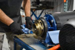
Step 1: Disassemble and Inspect
- Remove the pump from service per established lockout/tagout (LOTO) procedures and disassemble per the pump Operating and Instruction Manual
- Inspect the volute, diffuser(s), and impeller for evidence of erosion, corrosion, cavitation damage, or mechanical wear — replace components that show significant material loss or surface damage
- Replace all mechanical seals, gaskets, and bushings as a matter of course — these are wear components and should be replaced at every scheduled service interval regardless of apparent condition
- Check motor shaft axial and radial movement (shaft end play and shaft runout) — movement exceeding the manufacturer’s specified tolerance indicates bearing wear; replace motor bearings or the motor assembly as required
- Inspect suction and discharge connection threads and flanges for damage, corrosion, or erosion — refinish sealing surfaces or replace damaged connection hardware as needed
- Check the pump shaft for runout, straightness, and surface condition at all seal and bearing interface locations
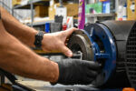
Step 2: Reassemble
- Reassemble the pump and motor in strict accordance with the pump and motor Operating and Instruction Manual — follow all torque specifications, clearance settings, and assembly sequences
- Install all new seals, gaskets, and O-rings — never reuse elastomeric sealing components
- Verify correct impeller clearance adjustment per the manufacturer’s specifications — improper impeller clearance reduces hydraulic efficiency and increases internal recirculation wear
Step 3: Recommission
- Follow the pump manufacturer’s installation and startup procedures for the specific pump model — do not skip steps or modify the startup sequence
- Verify correct rotation direction before starting
- Prime the pump fully before first start to prevent seal dry running during the critical initial startup period
- After restart, verify flow rate, discharge pressure, motor current, and seal condition — compare to baseline performance data to confirm the pump is performing to specification
| Service Item | Recommended Action / Interval |
| Mechanical seals | Replace at every PM service (12–18 months for 24/7 operation) |
| Gaskets and O-rings | Replace at every PM service — never reuse |
| Bushings and wear rings | Inspect and replace if clearance exceeds manufacturer’s tolerance |
| Impeller condition | Inspect for erosion, cavitation pitting, and corrosion — replace if material loss is significant |
| Volute / diffuser surfaces | Inspect for erosive wear and corrosion — replace if hydraulic performance is degraded |
| Motor shaft end play and runout | Check at every PM — replace bearings or motor if movement is excessive |
| Motor bearing lubrication | Per motor manufacturer’s specification (if lubrication points are present) |
| Suction and discharge connections | Inspect threads/flanges for damage at every PM service |
| Fluid pH (DI water / glycol systems) | Monitor periodically based on operating hours and temperature — change fluid on schedule |
| Pump performance baseline | Record flow, pressure, and motor current at commissioning and after each PM service |
Recognizing Warning Signs of Developing Pump Problems
The best time to address a pump problem is before it causes an unplanned failure. Operators and maintenance technicians who know what to look and listen for can identify developing problems during routine inspections and schedule corrective action during planned maintenance windows rather than responding to emergency breakdowns.
- Increased vibration or noise — bearing wear, impeller damage, cavitation, or misalignment all manifest as changes in pump vibration signature or operating noise
- Elevated motor current — a motor drawing more current than its commissioning baseline indicates increased internal resistance to flow, wear ring degradation, impeller damage, or mechanical binding
- Reduced flow or pressure — degraded hydraulic performance relative to the commissioning baseline indicates wear ring clearance increase, impeller wear or corrosion, or internal recirculation
- Visible seal leakage — any persistent, visible liquid leakage from the seal area warrants immediate seal inspection and likely replacement
- Elevated pump or motor operating temperature — abnormal thermal conditions indicate bearing problems, motor overload, loss of cooling flow, or operation far from BEP
- Unusual noise or banging — cavitation produces a characteristic crackling or gravel-in-a-pipe noise that should be investigated immediately, as cavitation causes rapid impeller erosion
Don’t wait for a pump to fail before addressing warning signs. A vibration measurement, motor current trending, or simple visual inspection during rounds can identify a developing problem weeks before it causes an unplanned shutdown — and the cost difference between a planned repair and an emergency replacement is enormous.
Conclusion: Pump Reliability Is a Program, Not a Repair
Centrifugal pumps are dependable, long-lived workhorses when they are correctly selected for the application, properly installed, operated within their design parameters, and maintained on a consistent preventive maintenance schedule. The principles outlined in this guide — proper location and piping, rigid foundation, minimized start/stop cycling, fluid quality management, and regular scheduled service — are the proven foundation of maximum pump reliability and minimum total cost of ownership.
Remember: a centrifugal pump and its driver are pieces of rotating machinery that require systematic preventive maintenance to achieve their full potential service life. Proper operation and consistent maintenance will deliver the long, trouble-free service life that a well-built pump is designed to provide.
Price Pump manufactures centrifugal pumps engineered for long-term reliability across a broad range of industrial, chemical processing, semiconductor, and water treatment applications. Our application engineering team is available to assist with pump selection, installation guidance, and preventive maintenance planning for your specific service conditions.
Have questions about pump installation, maintenance intervals, or operating condition impacts on pump life for your specific application? Contact Price Pump at sales@pricepump.com or visit www.pricepump.com — our engineering team is ready to help.